![]()
![]()
![]()
This tutorial is an advanced tutorial. It is not
really a pure OpenGl, it is more a mathematical application for opengl.
You should know some mathematical notions, all is not explained here !
You will learn in this tutorial how to move in a 3D environment. For this, I use some of my mathematical/mechanical learning.
I will introduced you how to control movement using keyboard/mouse.
For this, I use matrices
transformations.
It may not be the easiest nor the more efficient way to implement a camera. But, I've wanted to
implement a camera by my own and it works well :-)
The camera implemented here is semi-advanced one, it support all of this features :
- forward, backward, upward, downward, left and right deplacement
- x (look up/down) and y(head rotation) rotation
- Time based movement
- 3rd Person camera
- Actions : Walk, Run, Duck, Free fall/Jump (with gravity)
To understand all this tutorial, you need to know what is a matrix and apply some basis
manipulations like multiplying two matrices. Matrices will not be explain here.
The environment is a maze (labyrinth). The maze is generated at run-time with a basic maze generator implemented thanks to this good article :
http://www.sulaco.co.za/maze.htm.
You can compare advantages/disadvantages of a normal and a 3rd person view for a such environment.
This maze generator is not explained here, I think that if you read the article you should
understand it without any problems. I've added here to make a cool tutorial :-)
But there are no collision in this tutorial so you can go through walls !
![]()
Lets begin with some mechanical basis about coordinate system and
rotations.
This will be usefull for the position and the orientation of the camera (ie the viewer) in relation
to a fixed coordinate system.
A coordinate system is composed of 3 vectors X, Y and Z :
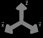
Right-handed Coordinate system
Suppose that we have a fixed coordinate system. To
position an object in this coordinate system, we have to know the position and
the orientation of this object in the fixed system.
This defines a second coordinate system relative associated to this object with X', Y' and Z' vectors.
The object considered is fix in this axis system.
In the following, the object considered is a camera.
So, the camera's position defines the eye position. The orientation of the camera defines the view
direction (Z' vector).
X', Y' and Z' vectors are the camera coordinate system.
Here is represented the fixe axix system (X,Y,Z) and the (moving) axis system
associted with the camera (X',Y',Z') :
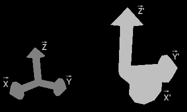
Camera system axis
The camera coordinate system is obtain by translating the fixed axis system (position of the camera). We have a temporary coordinate system (X1, Y1, Z1):
![]()
Position
Then, with a rotated of this temporary axis system camera and we have the camera
coordinate
system :
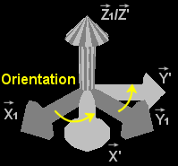
Orientation
I've choose to use Z' vector for the view direction (forward). The Y' vector for the upward vector. And
X' for the side vector (left because right-handed coordinate system).
The coordinate system is orthonormal ie it is orthogonale and normale.
The norm (magnitude) of the 3 vectors that define a coordinate sytem is always 1.
||X|| = ||Y|| = ||Z|| = 1
Moreover, vectors are orthogonale (perpendicular). These egalities are always true :
X = Y ^ Z
Y = Z ^ X
Z = X ^ Y
^ represent the cross product (vectoriel product).
These properties means that, if we know two vectors of magnitude 1 and orthogonal, we can clculate
the third vector to form an (orthogonal) coordinate system.
So, to represent a coordinate system, we just need to keep two of its vectors.
Warning : X, Y, Z represents a vector not a scalar (number).
There is two way to work with coordinate system for
the storage of his position/orientation.
We need to store the camera position (ie the center of the coordinate system) in a vector (camX, camY,
camZ). For the orientation :
- either store rotation angles.
- or, store X', Y'
and Z' vectors represented above (or just two due to the orthogonal property,
see above).
When
I've begin to implement a camera, this is the first way that come in mind. But, I've remark that it
is more complicated and need more time of calculation. More peoples seem to use forward/up vectors
instead of angles.
So, I've also implemented the second way during writting these tutorial.
Here are basic function of a camera :
![]() Move forwards /
backwards
Move forwards /
backwards
![]() Move on its sides
(ie Strafe)
Move on its sides
(ie Strafe)
![]() Turn around
up vector
Turn around
up vector
For a better camera, we will also add these features :
![]() Move upwards /
downwards
Move upwards /
downwards
![]() Turn around
side vector (look at the ground/sky).
Turn around
side vector (look at the ground/sky).
![]() Time based movement (Advanced part)
Time based movement (Advanced part)
![]() Action like walking, running, jumping ... (Advanced
part)
Action like walking, running, jumping ... (Advanced
part)
Here is describe basic function needed by all camera :
translation and rotation.
Notation used in this this tutorial.
Fixed coordinate system (X, Y, Z)
Camera coordinate system (X', Y', Z')
New camera coordinate system (X'', Y'', Z'') obtain after a transformation.
A vector V=(v1, v2, v3) expressed in the fixed coordinate system (X, Y, Z) can be written like this :
V = v1.X + v2.Y + v3.Z = |v1|
|v2|
|v3|
v1, v2 and v3 are scalars (number) -> Lower case
X, Y, Z are vectors
-> Upper case
Suppose this rotation around x vector :
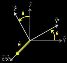
X Rotation
There is an easy way to represent this rotation : using matrices.
Effectively, there are pre-defined matrices to represent a rotation on an axis.
For example, the rotation around the x axis is represented by Rx (matrice
representing the transformation from original state (X,Y,Z) to final state
(X',Y',Z')) :
[Rx] = | 1 0 0 |
θ is the rotation angle
| 0 cosθ sinθ |
| 0 -sinθ cosθ |
Applying this transformation give these formulas:
(X',Y',Z') = [Rx] * (X,Y,Z)
ie
X' = 1.X + 0.Y + 0.Z = X ( and X = X'
Y' = 0.X + cosθ.Y + sinθ.Z = cosθ.Y+sinθ.Z
Y = cosθ.Y'-sinθ.Z'
Z' = 0.X - sinθ.Y + cosθ.Z = -sinθ.Y+cosθ.Z
Z = sinθ.Y'+cosθ.Z' )
There are similar matrices for y and z rotation :
[Ry] = | cosθ 0 -sinθ |
| 0 1 0 |
| sinθ 0 cosθ |
[Rz] = | cosθ sinθ 0 |
| -sinθ cosθ 0 |
| 0 0 1 |
How to use these rotation matrices ?
To expressed a vector V in the coordinate system (X, Y, Z) into a vector V' the coordinate system
(X', Y', Z'), use this relation :
V' = [Rx]-1 V
( [Rx]V' = [Rx][Rx]-1V => V = [Rx]V' )
[Rx]-1 is the inverse of [Rx].
In case of rotation matrices, the inverse of a matrice is the same than its
transposed matrix [Rx]T (easier to find a transposed matrix than an
inversed matrix).
[Rx]T = | 1 0 0
|T = | 1 0 0 |
T | 0 cosθ
sinθ |T | 0 cosθ
-sinθ |
T | 0
-sinθ
cosθ |T | 0 sinθ cosθ |
Similarly :
[Ry]T = | cosθ 0 -sinθ |T = | cosθ 0 sinθ |
T | 0 1 0 |T
| 0 1 0 |
T | sinθ 0 cosθ |T
| -sinθ 0 cosθ |
[Rz]T = | cosθ sinθ 0 |T = | cosθ
-sinθ 0 |
T |
-sinθ cosθ 0 |T
| sinθ cosθ 0 |
T | 0 0 1 |T
| 0 0 1 |
For the rotation represented above (X rotation), we have these egalities :
|V'x| = [Rx]T|Vx| = |Vx
|
|V'y| |Vy| |cosθ.Vy-sinθ.Vz|
|V'z| |Vz|
|sinθ.Vy+cosθ.Vz|
Remark :
You can expressed a vector V' in the coordinate system (X', Y', Z') into a vector V the
coordinate system (X, Y, Z), with this relation :
V = [Rx] V'
![]() APPLICATION
APPLICATION
Before that you're all lost, here is a little application of what we've seen until
now.
Suppose that the camera is position anywhere. The coordinate system of the camera
is represented by X', Y' and Z'.
You want to see on your sides, for example on your
left.
For that, you need to rotate from 90 degrees (ie PI/2 radians) around Y'.
This transformation is represented by this rotation matrix :
[Ry] = | cosθ 0 -sinθ | = | 0 0 -1 |
| 0 1 0 |
| 0 1 0 |
| sinθ 0 cosθ | | 1
0 0 |
So, relation between old (X',Y',Z') and new (X'',Y'',Z'') coordinate system is :
X'' = cosθ.X' - sinθ.Z' ( = -Z' )
Y'' = Y'
( =
Y' )
Z'' = sinθ.X' + cosθ.Z' ( = X' )
If before the rotation, the camera coordinate system is the same as the global
axis system (X, Y,
Z), we have :
X'' = | 0|
Y'' = |0|
Z'' = |1|
| 0| |1|
|0|
|-1| |0|
|0|
To translate the camera from a deplacement exprimated in the fixed coordinate system, we simply add the
current position and the deplacement. Because, the position of the camera is expressed in the
fixed coordinate system.
If the deplacement is expressed in the camera coordinate system (example, move forward). We first
have to expressed the deplacement in the fixed coordinate system before we can had him to the position.
![]() How to expressed a vector in the fixed coordinate system ?
How to expressed a vector in the fixed coordinate system ?
Suppose that we have a vector V=(v1, v2, v3) expressed in the camera coordinate system (X', Y', Z').
(v1, v2, v3 are scalar and X', Y,' Z' are vectors).
So, V = v1.X'+v2.Y'+v3.Z'
There is two way to calculate this previous formula.
1)
If we know the rotation around all axis, we can expressed X', Y' and Z' in function of X, Y, Z
using the rotation matrix.
ie
V = [R].|v1|
|v2|
|v3|
[R] is the rotation matrix, an association of basic rotation matrix on each
axis.
2)
If we know the coordinates of the axis vector of the moving axis system (X',Y',Z')
expressed in the fixed coordinate system, we just have to calculate :
V = v1.X'+v2.Y'+v3.Z' = v1.|X'_x|+v2.|Y'_x|+v3.|Z'_x| = |v1.X'_x + v2.Y'_x + v3.Z'_x |
|X'_y| |Y'_y| |Z'_y| |v1.X'_y + v2.Y'_y + v3.Z'_y |
|X'_z| |Y'_z| |Z'_z| |v1.X'_z + v2.Y'_z + v3.Z'_z |
with X'= |X'_x| Y'= |Y'_x| Z' = |Z'_x|
|X'_y| |Y'_y|
|Z'_y|
|X'_z| |Y'_z|
|Z'_z|
Submary :
Coordinates in the camera coordinate system axis :
V = |v1|
|v2|
|v3|
Coordinates in the fixed/global coordinate system is :
V = [R].|v1| = |v1.X'_x + v2.Y'_x + v3.Z'_x |
|v2| |v1.X'_y + v2.Y'_y + v3.Z'_y |
|v3| |v1.X'_z + v2.Y'_z + v3.Z'_z |
Remark :
You can deduce of this formula that
[R] = |X'_x Y'_x Z'_x | = |X' Y' Z'|
|X'_y Y'_y Z'_y |
|X'_z Y'_z Z'_z |
So, the tranformation matrix is linked to left/up/forward vectors (ie (X',Y',Z')
of the moving coordinate system.
![]() APPLICATION
APPLICATION
Suppose that we have the rotation view in the application of the rotation
section.
So
[R] = | 0 0 -1 |
| 0 1 0 |
| 1
0 0 |
or
X' = |0|
Y' = |0|
Z' = |-1|
|0| |1|
| 0|
|1| |0|
| 0|
We want to move forward ie along the +Z' vector.
So, V = |0| expressed in the camera coordinate system.
|0|
|1|
If we know the angles of rotation ie [R], the vector expressed in the fixed coordinate system is :
V = | 0 0 -1 |.|0| = |-1|
| 0 1 0 | |0| | 0|
| 1
0 0 | |1| | 0|
If we know X', Y' and Z' in the fixed coordinate system, we have :
V = |0.0 + 0.0 + 1.(-1)| = |-1|
|0.0 + 0.1 + 1.0 | | 0|
|0.1 + 0.0 + 1.0 | | 0|
Remark : we need to find the same result with the two methods !
We've seen two possible representations of an coordinate system
here. II will explain you how to implement a camera using each representation.
Let's begin with the first representation using position and angles relatively
to the fixed coordinate system.
Camera 1 |
|
//Position of the Camera in the fixed
axis system |
Vector3f is used to used to store 3 coordinates.
Position field store x, y and z coordinate of the camera in the fixed coordinate system.
Orientation store x, y and z rotation angles. z angle will be ignored. Just x and y angles will be
used here.
How to rotate ?
This is very simple, just increase angle like this :
Rotation |
|
public void rotate(float angleX, float angleY) |
How to move (translate) ?
To translate with a vector expressed in the fixed coordinate system, this is similar to the rotation
(ie increase the current position with the deplacement).
But, a such deplacement is not usefull to our camera. Effectivly, the deplacement is generally
expressed in the camera coordinate system.
So, we need to convert the deplacement expressed in the camera axis system to a deplacement in the
fixed coordinate system (the position of the camera is expressed in the fixed coordinate system).
To do this, we know the rotation angles. If you've read the translation
section, you should rememeber that we already seen this.
By using rotation angles, we can calculate the rotation matrix. Then, to make the conversion, we
just have to multiply this matrix with our deplacement expressed in the camera coordinate system :
Translation |
|
/* |
Warning :
[R] = [Ry][Rx] and NOT [R] = [Rx][Ry]
The order is important! We rotate first around y axis.
[Ry] = | cos(yRot) 0 -sin(yRot) | and
[Rx] = | 1 0 0 |
| 0 1 0 |
| 0 cos(xRot) sin(xRot) |
| sin(yRot) 0 cos(yRot) |
| 0 -sin(xRot) cos(xRot) |
We have :
[R] = | cos(yRot) sin(xRot)*sin(yRot) -cos(xRot)*sin(yRot) |
| 0 cos(xRot) sin(xRot) |
| sin(yRot) -sin(xRot)*cos(yRot) cos(xRot)*cos(yRot) |
How to position the camera ?
You know how to translate and rotate ou camera.
Here, we will see how to position our camera using gluLookAt.
This code should be called at
each beginning of the
drawing.
Positionning our camera |
|
//In Scene class |
Now, you've seen how to make a very basic camera.
Here, we will see how to make a Camera using the representation with
forward, up nd left vectors.
Camera 2 |
|
//Position of the Camera in the fixed
axis system |
How to rotate ?
To rotate, use the relation between old and new axis vectors.
And this property : when you rotate around an axis, vectors in this axis are not affected (ie remains the same).
You also know that the coordinate system is orthogonale, so :
Z = X ^ Y
X = Y ^ Z
Y = Z ^ X
Here is the process to make a rotation :
![]() For each rotation
a vector remains unchanged. Don't make any calcul for this vector.
For each rotation
a vector remains unchanged. Don't make any calcul for this vector.
![]() Now, you need to
calculates the 2 others vectors. Calculate just one vector using
rotation matrix.
Now, you need to
calculates the 2 others vectors. Calculate just one vector using
rotation matrix.
![]() For the last one, use the orthogonal property. This will avoid to stack up
calculation errors due to round of float and double.
This is also a good way to make sure that the coordinate system is always orthogonale.
For the last one, use the orthogonal property. This will avoid to stack up
calculation errors due to round of float and double.
This is also a good way to make sure that the coordinate system is always orthogonale.
It is also a idea to normalize vectors, even if it is not strictly necessary (with no round of
values, they should always remains normalized).
Rotation |
|
/** |
You can write the same implementation for the z (forward) rotation.
Be prudent, rotations are made to the current camera coordinate system. If you rotate
around y (up vector, it will rotate around your up vector of the camera coordinate system and not
the fixed one.
If you want to rotate around fixed axis system, here is one way to achieve this :
Rotation2 |
|
/** |
How to translate ?
Similarly to the first implementation, you need to convert the deplacement in the fixed coordinate
system. For this, use these formulas.
Translation |
|
/* |
How to position the camera ?
Positionning our camera |
|
//In Scene class |
The first implementation need more calculation, it should
calculate each time the expression with cos and sin (toVectorInFixedSystem1 from
lookAt) even if no transformations are made.
The second implementation store these operations (in left/up/forward vectors).
But, without angles datas, the second implementation have some restrictions compared to the first
implementation (can't bound simply angle).
=>
Instead of just keeping angles or left/up/forward vectors, you can keep both
angles and vectors.
![]()
In the first part we've seen all the theory, but our camera is not yet finished.
Effectivly, we need to call translate and rotate to move our camera. For that, we will implements
key and mouse listeners.
Keyboard will be used to move forward and straffe. For this, we will use arrow keys.
|
KeyListener (1) |
public void keyPressed(KeyEvent ke) |
If you use this, you will probably remark a problem : if you
press two or more keys, just the last generate a keypressed event.
A way to solve this problem is to store keys pressed :
|
KeyListener (2) |
|
public void keyPressed(KeyEvent ke) |
The update method of Camera is called at each frame. So, if a key is
pressed, call translate :
|
Update |
/* |
For the mouse it is a little different.
In most shooter games, the mouse (the sight) is always centered on the screen. I've chooser to use
the same method to rotate the camera.
Each time a mouse moved event is call, we compare the center of the frame with the cursor position.
|
Mouse motion listener |
|
private void mouseMoved(MouseEvent me) |
Problem, how to center the mouse ?
This can be done using the java.awt.Robot class.
Robot can be used to control the mouse, keyboard, make screen
captures ...
|
Robot |
|
private void centerTheMouse(Component component) |
![]()
This page is too long for advanced part, go here for
Advanced part.
Advanced part contains time based movement, third person view ...
![]()
The code is completly different in the sources than in this tutorial. Here, I've
tried to simplify the code
to make a 'step-by-step' tutorial.
So, read this tutorial if you've got difficulties with the code.
It will be cool if you can tell me what you think about this tutorial :-)
Remember to download the GraphicEngine-1.1.2 to run this tutorial !
Tutorial 26 src (578 ko) //Port to Jogl JSR-231 initially done by Magarrett Dias
If you've got any remarks on this tutorial, please let
me know to improve
it.
Thanks for your feedback.
![]()
![]()
| Copyright © 2004-2012 JĂ©rĂ´me Jouvie - All rights reserved. | http://jerome.jouvie.free.fr/ |